Main Content
Anode-Free Solid-State Batteries
Summary:
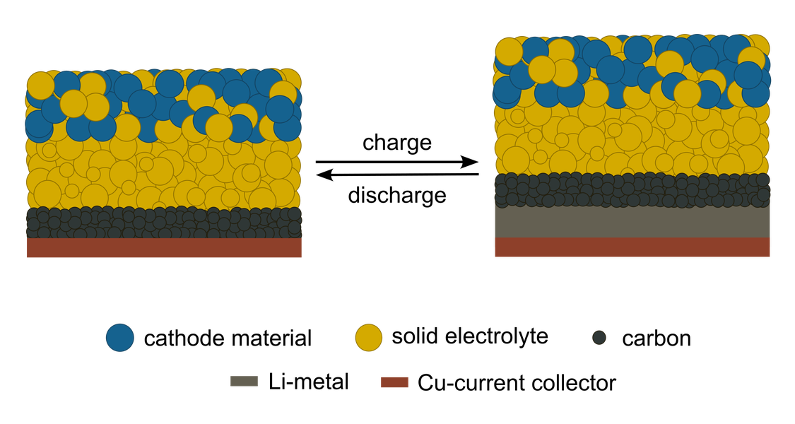
Anode-free solid-state batteries (AFSSBs) are expected to emerge as a next-generation energy storage technology. Unlike conventional lithium-metal batteries, which utilize a pre-formed lithium metal anode, AFSSBs do not require an anode active material during assembly. Instead, lithium is plated onto a bare current collector, acting as the working anode during the first charge (Figure 1). This simplifies the cell architecture and reduces the mass of inactive materials. Consequently, the greatest advantage of an anode-free solid-state battery is its significantly increased energy density.
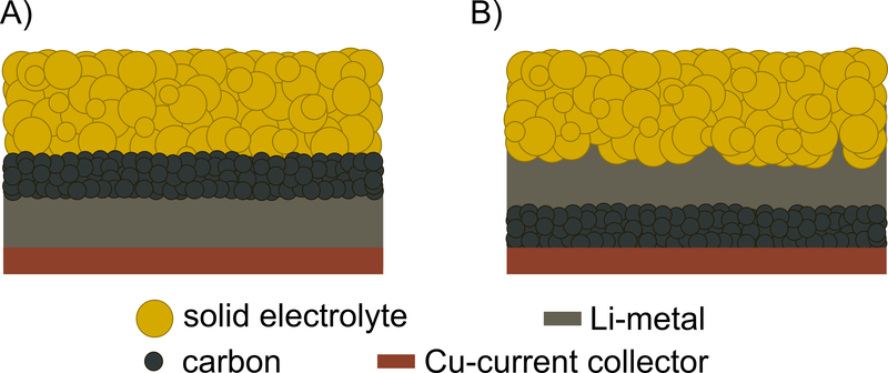
However, a major challenge remains a stable and reversible lithium plating and stripping without dendrite formation. To achieve this, an additional layer consisting of carbon particles is introduced to suppress dendrite formation by acting as a separator, keeping the solid electrolyte layer apart from the forming lithium metal layer and leading to a more uniform lithium deposition on the current collector. The described deposition of lithium at the current collector / carbon interface is shown in Figure 2.A. Undesired lithium plating at the carbon / solid electrolyte interface (Figure 2.B) should be prevented by a suitable design of the cell.
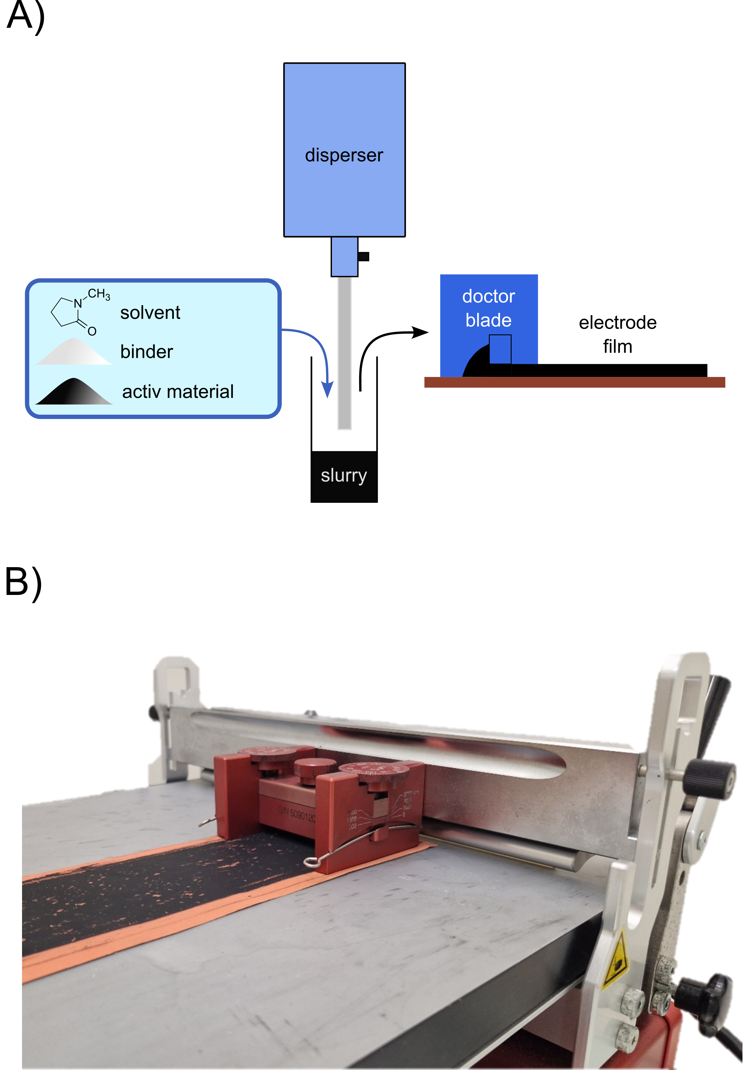
In our research group we manufacture different carbon interlayers by doctor blading a slurry onto a current collector (Figure 3). This slurry contains the desired carbon particles, a polymeric binder (PVDF) and an organic solvent that evaporates during the drying process. We study the performance of the different carbon interlayers in solid-state batteries. Furthermore, we investigate the forming interphases on the anode site.
Contact Person:
Highlighted Publications:
- Y.-G. Lee S. Fujiki et al., 'High-energy long-cycling all-solid-state lithium metal batteries enabled by silver–carbon composite anodes', Nat. Energy 5 (2020), 299–308. doi:10.1038/s41560-020-0575-z
- D. W. Liao, D. Zeng et al., 'Effects of Interfacial Adhesion on Lithium Plating Location in Solid-State Batteries with Carbon Interlayers', Adv. Mater. 37 (2025), 2502114. doi:10.1002/adma.202502114