Main Content
Ionic current rectification in a nanochannel–nanofunnel device
We studied ionic current rectification observed in a nanofluidic device with a nanofunnel positioned between two straight nanochannels. Ion transport is simulated by resolving the coupled three-dimensional Nernst–Planck, Poisson, and Navier–Stokes equations. In the modeled system, the electric double layer extends into the channel, and consequently, the funnel tip exhibits charge-selective properties, which results in the formation of enriched and depleted concentration polarization (CP) zones within the nanofunnel in the high- and low-conductance (HG and LG) states, respectively. This scenario is similar to the one observed for ion transport through a charged conical nanopore connecting two macroscopic reservoirs. However, the presence of the adjacent straight nanochannels allows the CP zones to propagate out of the funnel into the adjoining channels. The condition for propagation of the CP zones is determined by several parameters, including the electroosmotic flow velocity. We demonstrate that in the HG regime the modeled system is characterized by increased ionic concentrations in the entire cathodic nanochannel, whereas in the LG state the depleted CP zone does not propagate out of the funnel and remains localized. The required three-dimensional modeling scheme is implemented on a parallel computational platform, is general as well as numerically efficient, and will be useful in the study of more advanced nanofluidic device designs for tailoring ionic current rectification.
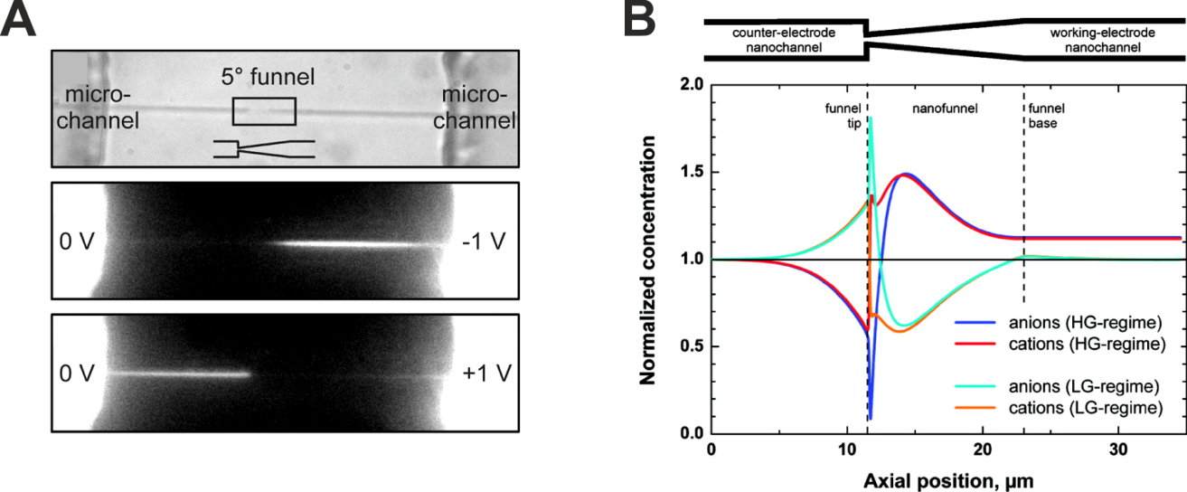
Figure 1: (A) Bright-field image of the 5° funnel and nanochannels connecting two microchannels (top) and fluorescence images of disodium fluorescein transported through the device in the HG regime (middle) and LG regime (bottom). The inset in the top panel is a schematic of the funnel with the rectangle highlighting its position along the 85 μm long nanochannel. (B) Simulated normalized concentrations of cations and anions along the centerline of the system with a 5° funnel (filled with 1 mM potassium chloride solution) for the HG and LG regimes (surface charge density: −5 mC/m2, applied electric field strength: ±11.765 kV/m). Dashed lines indicate the location of funnel tip and base.