Main Content
Confined particulate packings in cylindrical and non-cylindrical conduit geometries with different bed density and aspect ratio, i.e., ratio of conduit characteristic transverse length to particle size
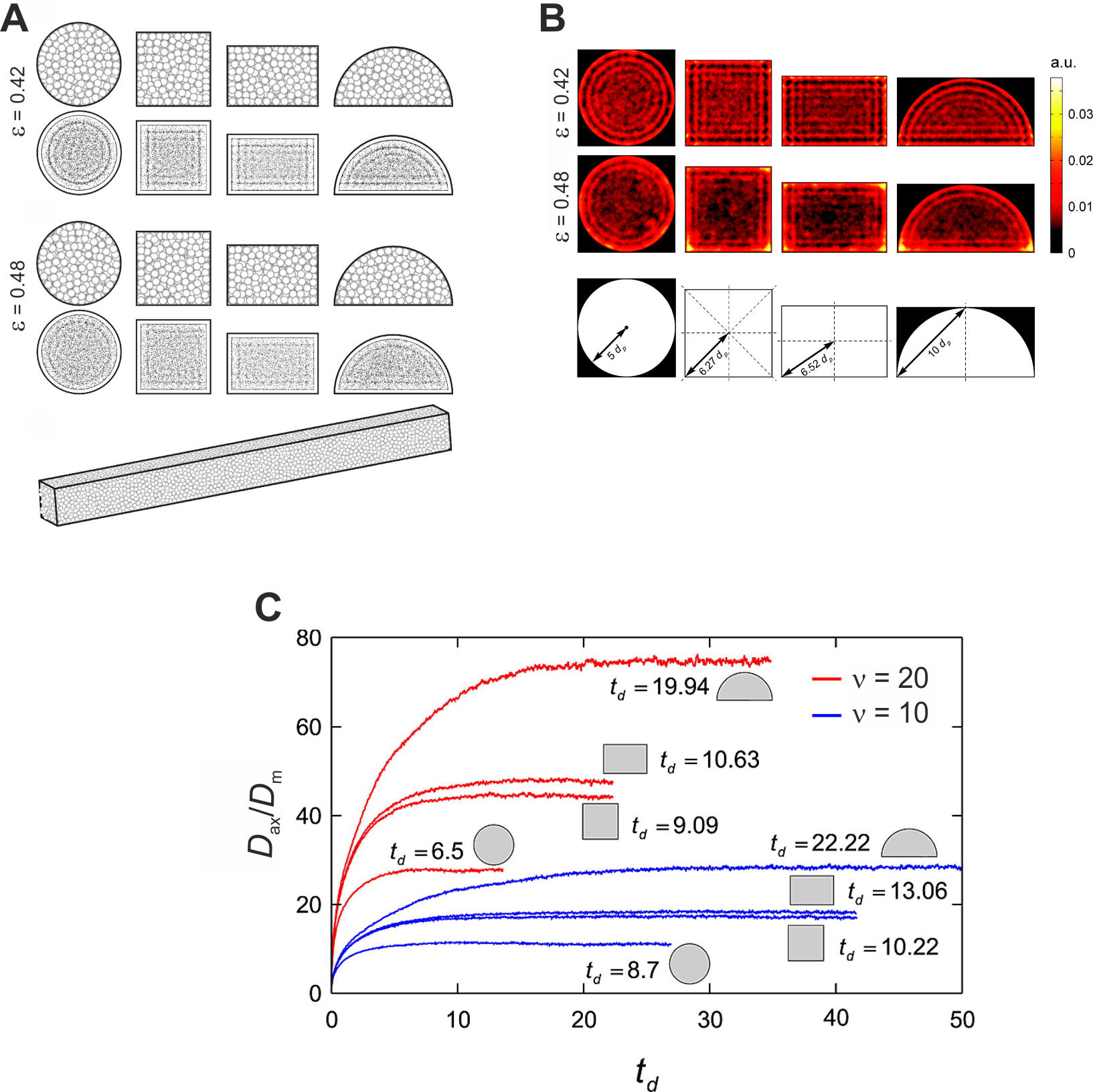
Panel A. Confined sphere packings simulated for containers with four different cross-sectional geometries: circular, quadratic, rectangular, semicircular. Packings with two different bed porosities (0.42 and 0.48) were generated for each container geometry. Shown are the front of the generated packings and projections of all particle centers in a packing onto the front plane. All packings have identical cross-sectional area. At the bottom, a side view of a packing with quadratic cross-section is shown.
Panel B. Velocity profiles for packings with the four different cross-sectional geometries at two selected bed porosities (0.42, top row, and 0.48, center row). The reduced velocity uavdp/Dm (where uav is the average flow velocity through a packing and Dm the bulk molecular diffusion coefficient) is 10. The schematic (bottom row) illustrates the characteristic transverse length for each velocity field (conduit geometry). It corresponds to the distance that needs to be covered in order to realize a complete exchange (equilibration) between different local velocities.
Panel C. Normalized axial dispersion coefficient of an inert tracer as a function of the dimensionless diffusive time td = 2Dmt/dp2 for fixed beds with a porosity of 0.48. For each container geometry, two curves are shown, one calculated at a reduced velocity of 10 (blue lines) and at a reduced velocity of 20 (red lines). Each curve represents an average of three independent calculations starting with the generation of packings from three different seeds. The actual values for td provided in the figure represent the time for each geometry (and value of reduced velocity) after which asymptotic behavior in Dax/Dm is observed.